
Flex PCB 제조업체
20년 이상의 신뢰
ISO 9001|ISO 13485|IATF 16949
업계 리더들의 신뢰


설계 파일 업로드
Gerber 파일을 업로드하시면 24시간 내에 견적을 받아보실 수 있습니다.
15년+
제조 경험
2,500+
서비스 고객
50K sqm
월간 생산량
99%
정시 납품률
제조 능력
첨단 연성 PCB 제조 기술
최첨단 장비와 숙련된 기술진이 가장 까다로운 사양도 충족시킵니다.
산업 분야
다양한 산업 분야에 서비스 제공

의료기기
진단 장비, 이식형 기기, 의료 영상 시스템을 위한 ISO 13485 인증 제조.

자동차
센서, 디스플레이, 제어 시스템을 위한 IATF 16949 준수 연성 회로.

항공우주 & 방위
항공전자, 위성, 방위 시스템을 위한 고신뢰성 연성 PCB.

소비자 가전
스마트폰, 웨어러블, 휴대용 기기를 위한 소형화된 연성 회로.
산업 응용 제품 쇼케이스
다양한 산업을 위해 설계된 리지드-플렉스 PCB 제품을 확인하세요
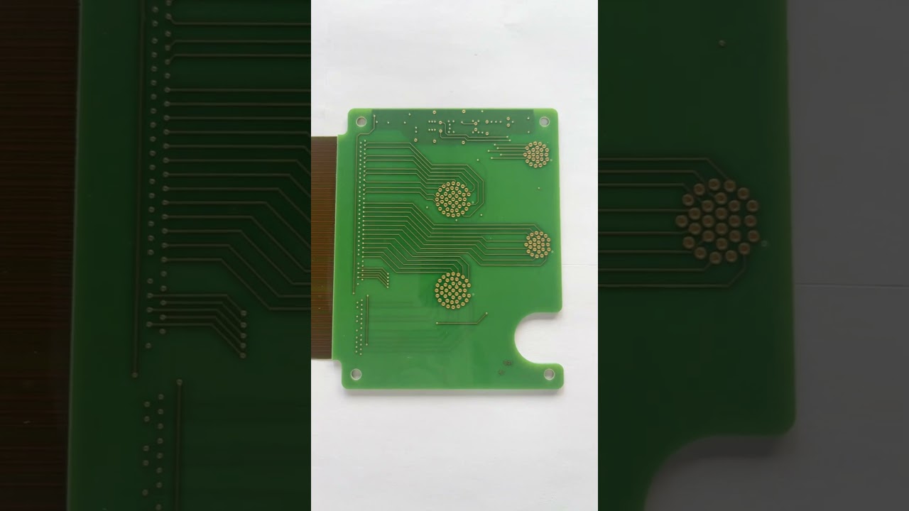
소비자 전자제품용 리지드-플렉스 PCB
소비자 전자기기를 위한 컴팩트한 리지드-플렉스 솔루션
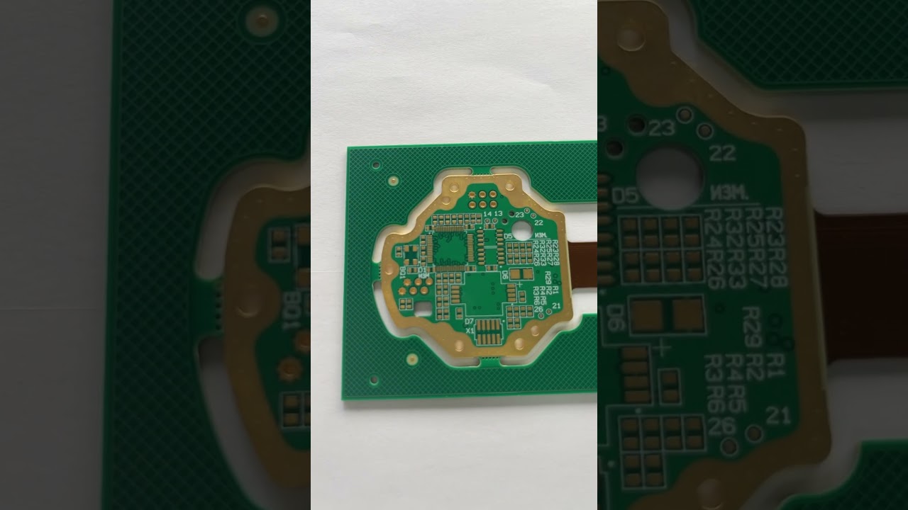
산업 제어용 4층 리지드-플렉스 보드
산업 자동화 시스템을 위한 고신뢰성 리지드-플렉스
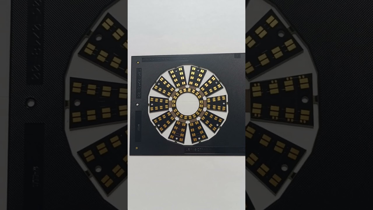
의료 기기용 리지드-플렉스 PCB
의료 기기 응용을 위한 맞춤형 리지드-플렉스 솔루션
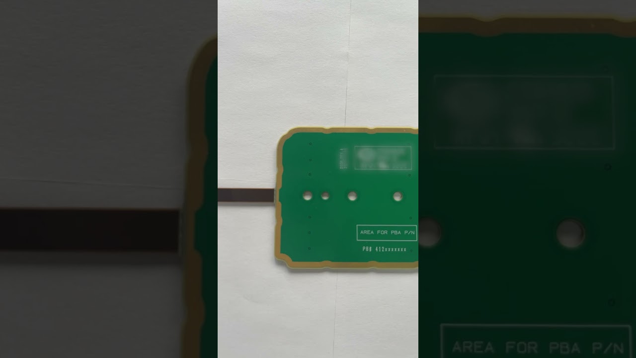
소비자 전자제품용 리지드-플렉스 PCB
휴대용 소비자 제품을 위한 첨단 리지드-플렉스 설계
FlexiPCB - 연성 PCB 제조의 선도 기업
FlexiPCB는 15년 이상의 경험을 보유한 연성 및 리지드-플렉스 PCB 전문 제조업체입니다. 최첨단 시설과 ISO 인증 품질 관리 시스템으로 전 세계 고객에게 서비스를 제공합니다.

자주 묻는 질문