
Produttore di Flex PCB
Affidabilità da oltre 20 anni
Fidato dai leader del settore


Ottieni il Tuo Preventivo Istantaneo
Carica i tuoi file Gerber per un'analisi DFM istantanea e prezzi competitivi.
Ingegneria per la Flessibilita
I nostri processi sono progettati per gestire le sfide geometriche uniche dei circuiti flessibili, dalla piegatura dinamica alla piegatura stretta.
Prototipazione Rapida
- Consegna 24 Ore
- Nessuna Quantita Minima
- Verifica DFM Inclusa
- Imaging Laser Diretto
Ingegneria di Precisione
- Min Pista/Spazio: 3mil
- Min Foro: 0.1mm
- Via Ciechi e Sepolti
- ENIG e Oro Duro
Settori Alimentati dai Nostri Circuiti

Dispositivi Medici
Circuiti flessibili affidabili per impianti, monitor e robotica chirurgica.

Aerospaziale e Difesa
Schede rigido-flex ad alta affidabilita conformi agli standard MIL-SPEC.

Automotive
PCB durevoli per sensori, infotainment e connessioni ECU.

Elettronica di Consumo
Circuiti compatti e pieghevoli per wearable e dispositivi mobili.
Vetrina delle Applicazioni Industriali
Scopri i nostri prodotti PCB rigido-flessibili progettati per varie industrie
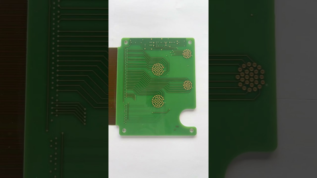
PCB Rigido-Flessibile per Elettronica di Consumo
Soluzioni rigido-flessibili compatte per dispositivi elettronici di consumo
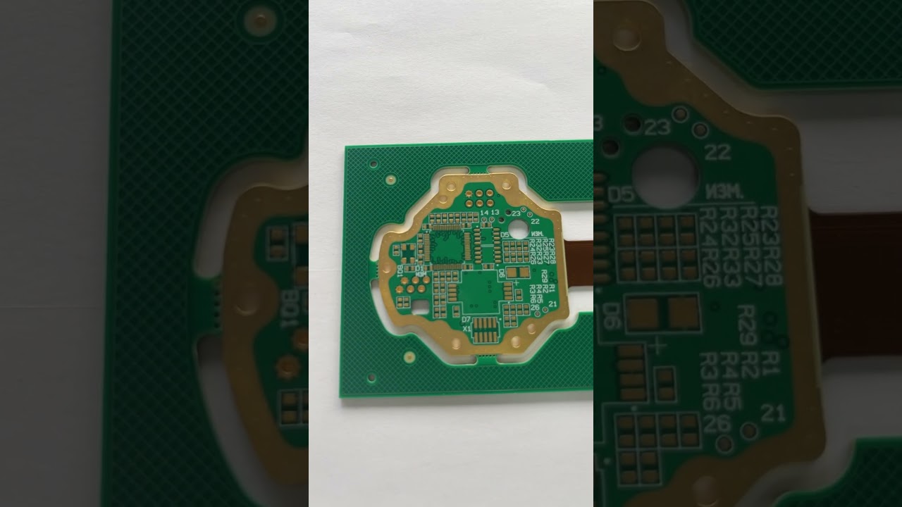
Scheda Rigido-Flessibile a 4 Strati per Controllo Industriale
Rigido-flessibile ad alta affidabilita per sistemi di automazione industriale
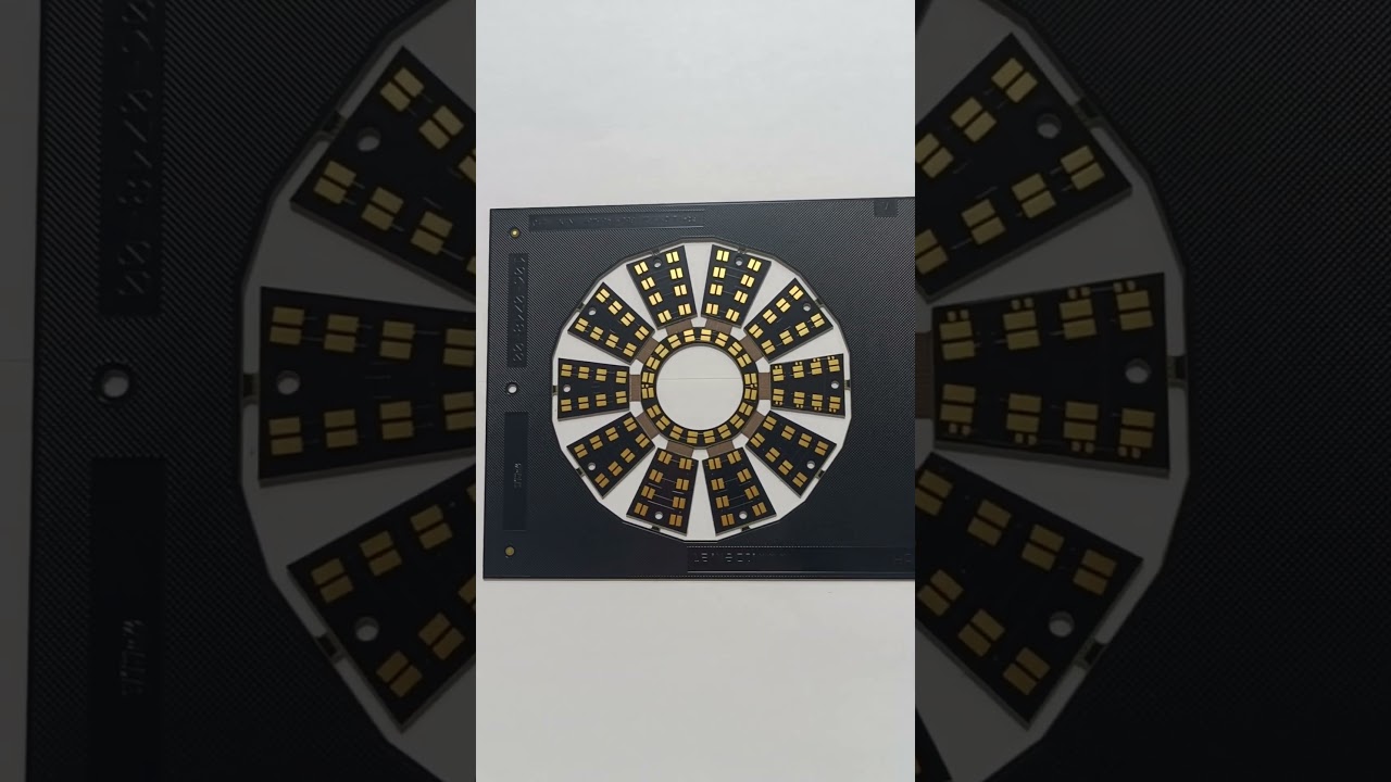
PCB Rigido-Flessibile per Dispositivi Medici
Soluzioni rigido-flessibili personalizzate per applicazioni di dispositivi medici
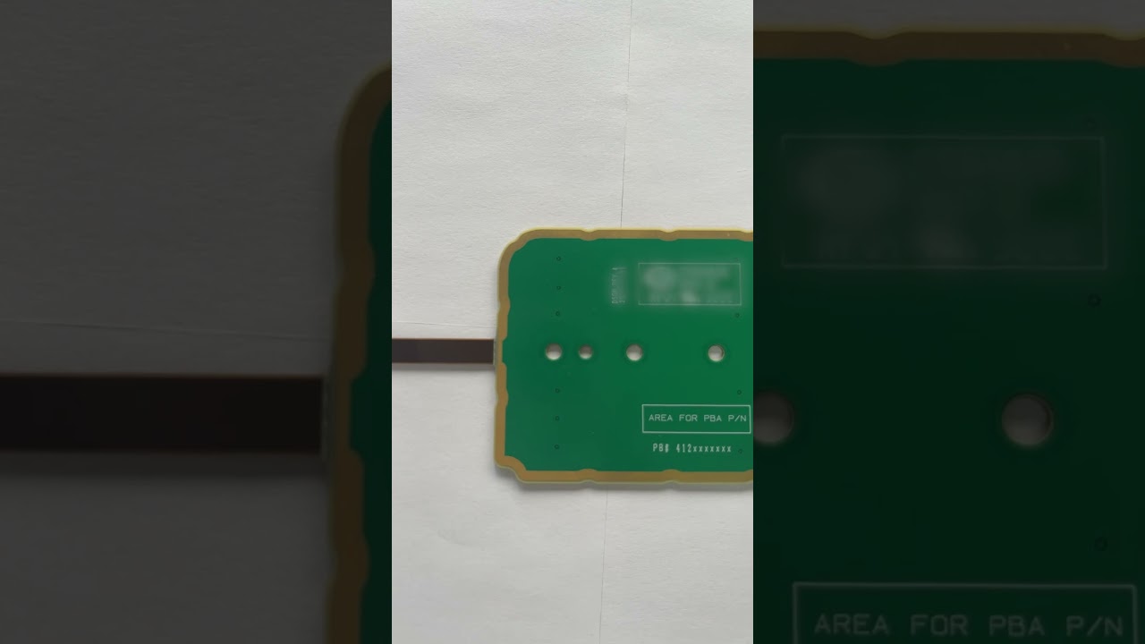
PCB Rigido-Flessibile per Elettronica di Consumo
Design rigido-flessibile avanzato per prodotti di consumo portatili
Perche Scegliere FlexiPCB per le Tue Esigenze di Circuiti Flessibili?
FlexiPCB e un produttore leader di circuiti stampati flessibili (Flex PCB) e PCB rigido-flessibili, servendo clienti in tutto il mondo con soluzioni di alta qualita e precisione. Il nostro impianto di produzione all'avanguardia combina tecnologia avanzata con decenni di esperienza per fornire circuiti flessibili che soddisfano le specifiche piu esigenti.
Ci specializziamo in una vasta gamma di applicazioni di Flex PCB, dai circuiti flessibili a singolo strato agli assemblaggi rigido-flex multistrato complessi. Le nostre capacita includono tecnologia HDI, impedenza controllata e varie finiture superficiali tra cui ENIG, OSP e placcatura in oro duro.

Con certificazioni ISO 9001:2015, ISO 13485 (Medicale) e IATF 16949 (Automotive), garantiamo qualita costante su tutti i nostri prodotti. Il nostro impegno per l'eccellenza ci ha resi un partner affidabile per settori tra cui dispositivi medici, aerospaziale, automotive ed elettronica di consumo.