
Vyrobce Flex PCB
Duveryhodny jiz vice nez 20 let
Duveruje nam prumyslovi lidri


Ziskejte okamzitou cenovou nabidku
Nahrajte sve Gerber soubory pro okamzitou DFM analyzu a konkurencni ceny.
Inzenyrstvi pro flexibilitu
Nase procesy jsou navrzeny tak, aby zvladly jedinecne geometricke vyzvy flexibilnich obvodu, od dynamickeho ohybani az po tesne skladani.
Rigid-Flex technologie
- 2-50 vrstev
- HDI mikroprokovy
- Bookbinder konstrukce
- Kontrolovana impedance
Rychle prototypovani
- 24hodinova doba dodani
- Zadne minimalni mnozstvi
- DFM kontrola zahrnuta
- Laserove primé zobrazení
Presne inzenyrstvi
- Min. cesta/mezera: 3mil
- Min. otvor: 0,1mm
- Slepe a zahrabe prokovy
- ENIG a tvrde zlato
Prumyslova odvetvi pohanena nasimi obvody

Zdravotnicka zarizeni
Spolehlive flexibilni obvody pro implantaty, monitory a chirurgickou robotiku.

Letectvi a obrana
Vysoce spolehlive rigid-flex desky splnujici normy MIL-SPEC.

Automobilovy prumysl
Odolne PCB pro senzory, infotainment a pripojeni ridicich jednotek.

Spotrebni elektronika
Kompaktni, skladatelne obvody pro nositelna zarizeni a mobilni pristroje.
Prezentace prumyslovych aplikaci
Podivejte se na nase rigid-flex PCB produkty navrzene pro ruzna prumyslova odvetvi
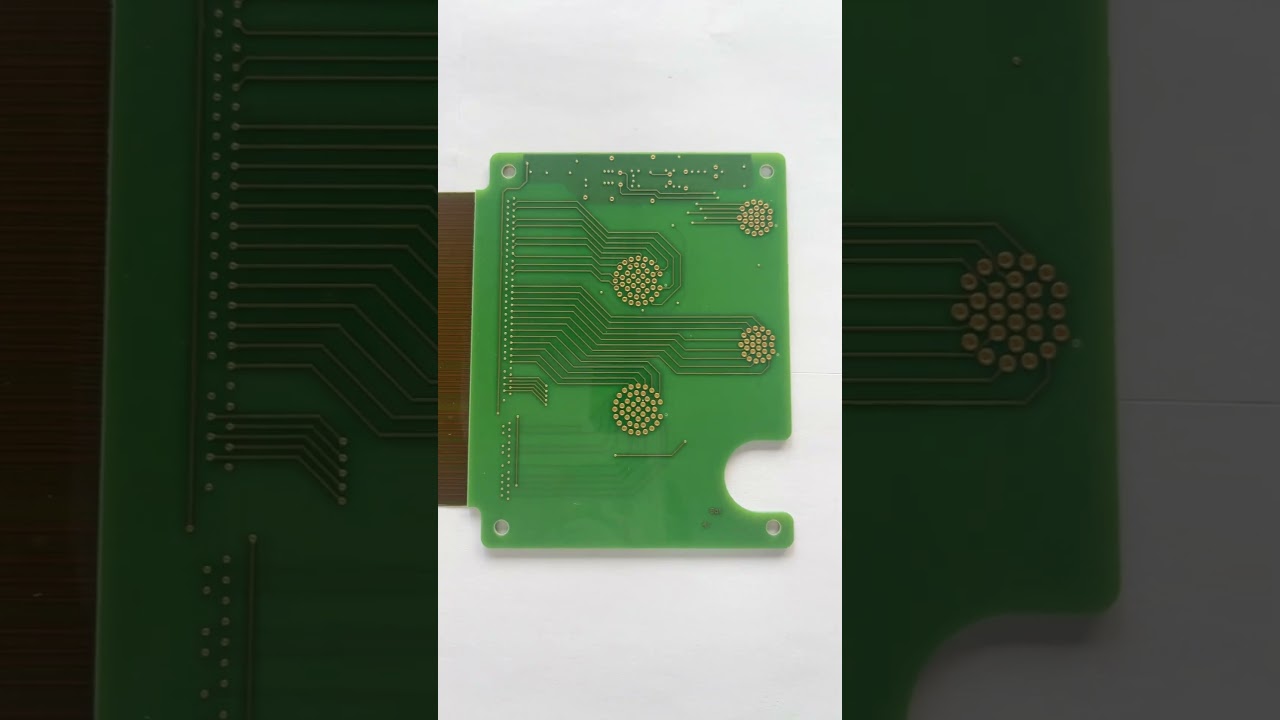
Rigid-Flex PCB pro spotrebni elektroniku
Kompaktni rigid-flex reseni pro spotrebni elektronicka zarizeni
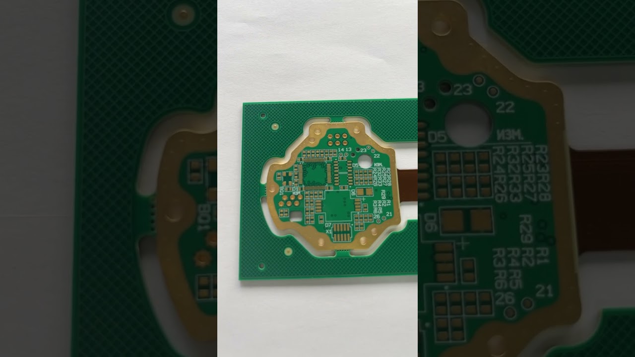
4vrstva Rigid-Flex deska pro prumyslove rizeni
Vysoce spolehlive rigid-flex pro systemy prumyslove automatizace
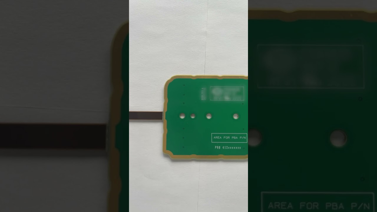
Rigid-Flex PCB pro zdravotnicka zarizeni
Pristizena rigid-flex reseni pro aplikace zdravotnickych pristroju
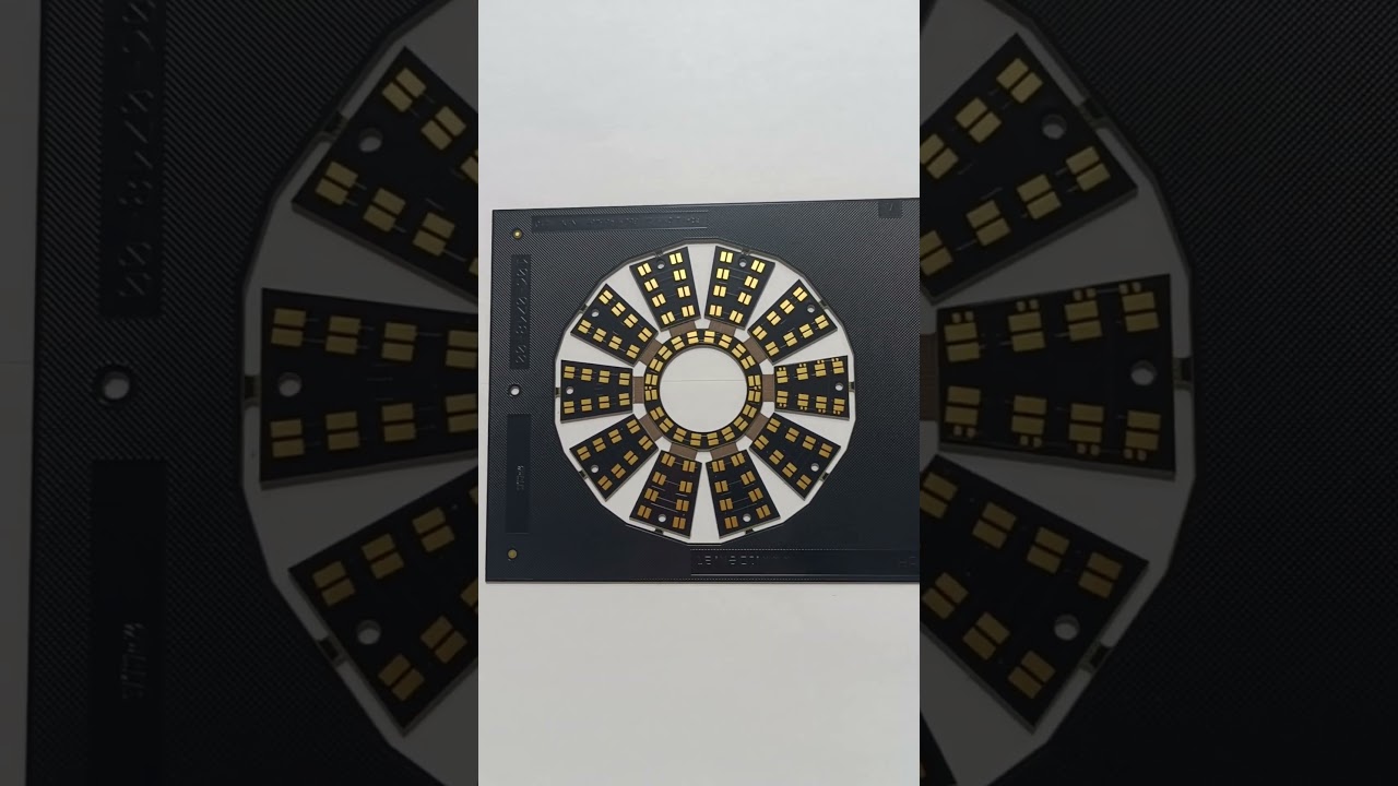
Rigid-Flex PCB pro spotrebni elektroniku
Pokrocily rigid-flex design pro prenosne spotrebni produkty
Proc si vybrat FlexiPCB pro vase potreby flexibilnich obvodu?
FlexiPCB je prednim vyrobcem flexibilnich tistenych spoju (Flex PCB) a rigid-flex PCB, ktery obsluhuje zakazniky po celem svete s vysoce kvalitnimi, presne navrzenymi resenimi. Nase nejmodernejsi vyrobni zarizeni kombinuje pokrocile technologie s desetiletimi zkusenostmi pro dodani flexibilnich obvodu, ktere splnuji ty nejnarocnejsi specifikace.
Specializujeme se na sirokou skalu aplikaci flex PCB, od jednovrstvych flexibilnich obvodu az po slozite vicevrste rigid-flex sestavy. Nase moznosti zahrnuji HDI technologii, kontrolovanou impedanci a ruzne povrchove upravy vcetne ENIG, OSP a tvrdého pozlaceni.

S certifikacemi ISO 9001:2015, ISO 13485 (zdravotnictvi) a IATF 16949 (automobilovy prumysl) zajistujeme konzistentni kvalitu vsech nasich produktu. Nas zavazek k dokonalosti z nas ucinil duveryhodneho partnera pro prumyslova odvetvi jako jsou zdravotnicka zarizeni, letectvi, automobilovy prumysl a spotrebni elektronika.