
Rigid-flex PCB design is transforming how we build our electrical systems and appliances as they have the benefits of both rigid and flexible PCBs.
Due to their flexibility and reliability, manufacturers can install PCBs in smaller areas.
The benefit alone means that manufacturers design devices with minimal space for PCB installation.
However, rigid-flex PCBs are generally more challenging to design than other PCBs.
But there’s no need to worry.
In today’s article, we’ll review important aspects of rigid-PCB design. Let’s get going.
Table of Contents
- What Are Rigid-Flex PCBs
- Rigid-Flex PCB Design Guidelines
- Applications of Rigid-Flex Circuit Boards
- The Rigid-Flexible PCB Design Challenges
- FAQs
- Conclusion
What Are Rigid-Flex PCBs
We need to know what rigid and flexible printed circuit boards are to understand what rigid-flex PCBs are.
Rigid PCBs are circuit boards whose substrate material is rigid.
As a result, they cannot bend or twist with the application of a force.
On the other hand, flexible PCBs are circuit boards that can bend, twist, or move in any direction with a 3-D space.
Now, rigid-flex PCBs combine both rigid and flexible PCB technologies.
As such, some sections are flexible, while others are rigid.
Moreover, they are lightweight and stable under vibrations and humid environments.
Rigid-Flex PCB Design Guidelines
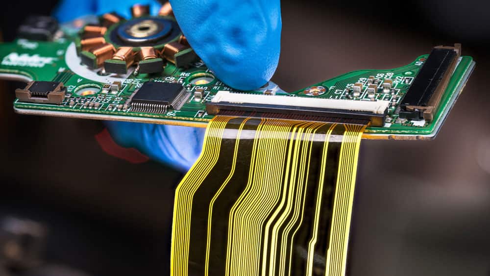
(Rigid PCB with a flexible cable)
Layout Guidelines
- First, keep the trace spacing and width as wide as possible in the flexible sections of your PCB.
- Second, do the solder pad and track connections roundly like a teardrop.
- Third, keep the soldering surfaces and annular rings wide as possible.
- Fourth, add stiffeners to your PCB to reach a 0.2 to 1-millimeter thickness.
Coverlay
Add coverlay to your printed circuit board to protect the conductors from environmental hazards.
Furthermore, the coverlay holds the pads to make your work easier when soldering.
Pads and Vias
Use pads that have tie-downs to ensure that the base material and copper metal foil attach during assembly.
Moreover, fillet the pads to lower the chances of breakage and stress points during flexing.
Concerning the vias, you can go with plated vias or blind vias.
Blind vias connect the outer layer to an adjacent layer and stop there.
On the other hand, plated vias run through the PCB, connecting all layers.
Defining Bending Radius
The flexible parts of the PCB have limits when it comes to how much you can bend them to ensure that they don’t break.
Make the bend radius at least 0.05 inches from a plated via to be safe.
Furthermore, it should be 10 times the thickness of the material.
Ground Plane
Crosshatch the ground planes to reduce overall design weight and improve circuit flexibility.
Moreover, keep the opening size proportional to the requirements to retain the shielding.
Applications of Rigid-Flex Circuit Boards
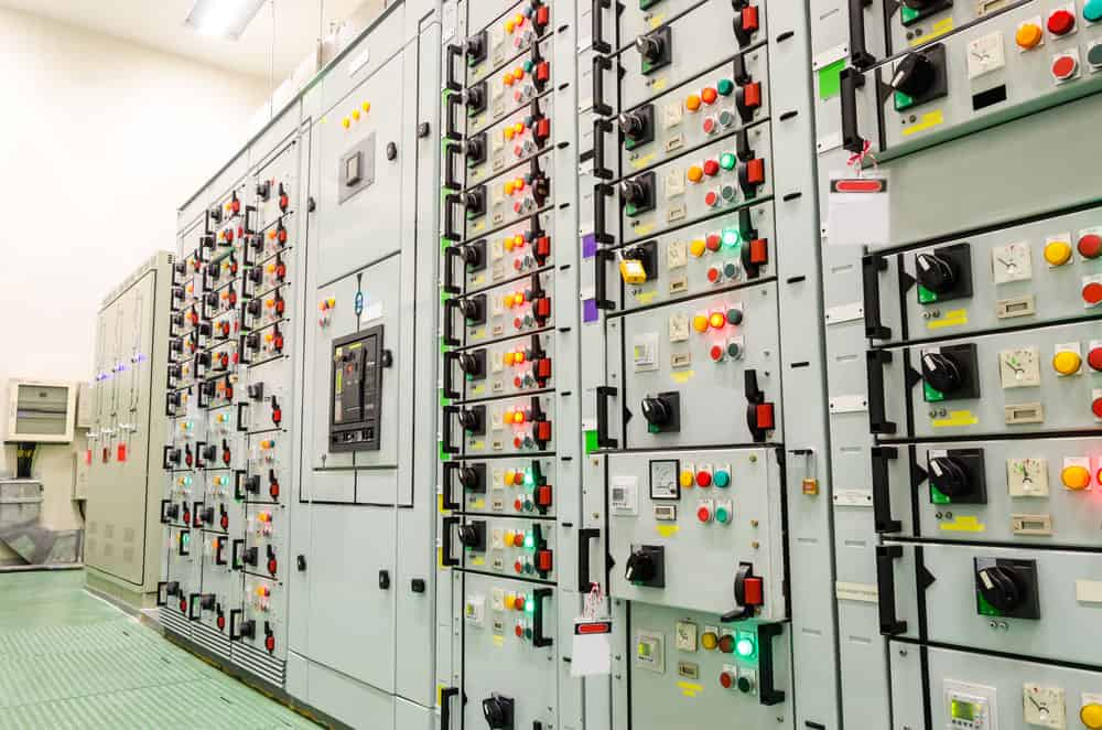
(Smart industrial power distribution switch gear)
During its earlier days, engineers used rigid-flex PCBs primarily in military and aerospace applications.
Over time, they are gaining popularity in consumer products across homes and business applications, whereby durability is a factor.
Here are some applications of the rigid-flex PCBs.
Industrial Application
Rigid-flex PCBs are better than rigid circuit boards in industrial applications that operate under immense stress or vibrations.
For instance, they are popular in power distribution systems and communication technologies.
Additionally, their compact size accommodates smaller, more effective sensors in irregular spaces.
Wearable Devices
The primary reason for using rigid-flex PCBs in medical and wearable devices is that they are lightweight and reliable.
Therefore they are popular circuit boards in wearable devices like smart clothes, fitness trackers, and smartwatches.
Doctors who monitor patients over long durations can’t use heavy monitoring devices in the medical field.
Device manufacturers opt for rigid-flex PCBs to reduce weight and allow doctors to monitor patients effectively.
Electronic Commerce
There’s a great demand for rigid-flex circuit boards in the E-commerce sectors like online retail businesses.
For instance, logistics companies use lightweight, powerful electronics to scan and track the movement of goods.
Modern-day trackers have rigid-flex PCBs to ensure longevity, especially if tracking vehicles subject them to stress.
The Rigid-Flexible PCB Design Challenges

(Two engineers discussing a PCB)
Designing rigid-flex PCBs is a challenging process that, if poorly managed, can lead to product failure and reliability issues.
As such, here are some design challenges that you may encounter.
Special Layer Types
Special layer types like stiffeners, cover layers, and adhesives are important parts of your rigid-flex PCB.
As such, you’ll have to define them when designing the layer stack-up.
A cover layer protects your circuit board metal layer against wear and tear.
It’s like a solder mask but offers better protection.
Additionally, it improves adhesion by making the base material stick to the metal foil.
On the other hand, stiffeners harden sections of the flexible PCB to allow component assembly.
Several PCB Outlines, All With Their Layer Stack-up
Rigid-flex PCBs have many layers, each with its unique layer stack-up.
When designing, ensure to define the stack-ups so that the subsequent processes like fabrication can use it.
Additionally, name each PCB outline so that it is easier to identify when they overlap.
Bending of the Rigid-Flex PCB
The flexible section of your rigid-flex PCB bends when manufacturing and after installing it.
Therefore, you need to define how it will bend and which sections of the design shall fold.
Additionally, define its bend radius or the sharpness with which your design bends.
Analyse Manufacturability

(Pick and place machine installing components on a PCB)
Manufacturing the flex section is more challenging than the rigid section.
Consequently, ensure manufacturability by running DFM checks at every stage of the layout process.
Additionally, run DFM checks on your flex circuitry during the product release.
Check Power and Signal Integrity
Most rigid-flex PCBs need a certain power and signal integrity analysis during design.
In set-ups with several flexible and rigid stack-ups, you must model properly to get the right analysis report.
FAQs
What are the rigid-flex PCB design materials?
Rigid-flex PCBs combine flexible and rigid PCB technologies.
The rigid part consists of materials like FR-4 or any other hard laminate.
Additionally, rigid materials usually consist of epoxy resin and fiberglass cloth for sufficient rigidity.
On the other hand, the flexible sections consist of polyimide or polyester films.
Therefore, they are durable and have excellent thermal stability.
Other materials include copper conductive traces and adhesives for bonding the different layers.
How many types of rigid-flex PCBs do we have?
We have three broad classifications of rigid-flex printed circuit boards.
First is the single-sided PCBs that comprise a single layer of conductive copper traces.
It is a simple PCB as it generally has a layer of flexible and rigid materials.
Second is the double-sided PCB with two layers of both the flexible and rigid PCBs.
Furthermore, it has conductive traces on both sides of the board.
The third type is the multi-layer PCB with more than two layers of rigid and flexible materials.
Moreover, it has conductive copper traces on several layers depending on the design.
Due to their complexity, engineers use them for power generation, military, and aerospace applications.
How complex is the rigid-flex PCB design process?
How complex a design process is depends on the equipment and level of skill that you have.
However, the design of rigid-flex PCBs tends to be more complex than other PCBs since it combines two different technologies.
Additionally, the design process has unique challenges, like determining the layer stack up and joining the rigid and flex sections.
If you have the right skill, you will find the process more intriguing rather than challenging.
Conclusion
Printed circuit boards are important parts of our electrical and electronic systems.
As time passes and technology evolves, there’s a need to develop better ones.
And as of today, rigid-flex PCBs are transforming the PCB industry.
Remember, it takes practice before one can fully master the rigid-flex PCB design.
Luckily, we’ve gone through important aspects of the design process.
All you need to do is put the knowledge into practice and manufacture a circuit board you are proud of.