
The ever-evolving trends in the electronics industry gave rise to a new type of multilayer circuit, the multilayer rigid, flexible PCB.
Like the standard multilayer PCB, this circuit board provides the flexibility that’s the cornerstone of many design concepts.
In addition, it weighs much less and takes up minimal space, enabling component and circuitry density, not to mention its reliability in extreme environments.
This article discusses this board’s functionality, features, and application.
Table of Contents
- What Is a Multilayer Rigid Flex PCB?
- What Is a Multilayer Rigid-Flex HDI PCB?
- Multilayer Rigid-Flex PCB Features
- Multilayer Flex Rigid PCB Design Considerations
- Multilayer Flex Rigid PCB Applications
- Advantages of Multilayer Flex Rigid PCBs
- FAQs
- Conclusion
What Is a Multilayer Rigid Flex PCB?
The multilayer rigid-flex PCB is a type of printed circuit board that consists of several layers of circuitries.
It uses PET ((polyethylene terephthalate) or PI (polyimide) as its substrate and has laminate technology.
The simplest version of the multilayer rigid flex multilayer PCB is the 3 Layer PCB.
It’s also the easiest of the multilayer rigid, flexible PCBs to create, and all engineers do is apply two copper shielding layers on each side of a one-sided flex PCB.
It’s the equivalent of a coaxial wire or shielding for a wire regarding electrical performance.
And as far as popularity goes, the most widely used multilayer flex PCB is the 4 Layer structure that utilizes metalized holes to achieve interlayer connectivity.
Usually, the two layers found in the middle of the 4 Layer board are the power and ground layers.
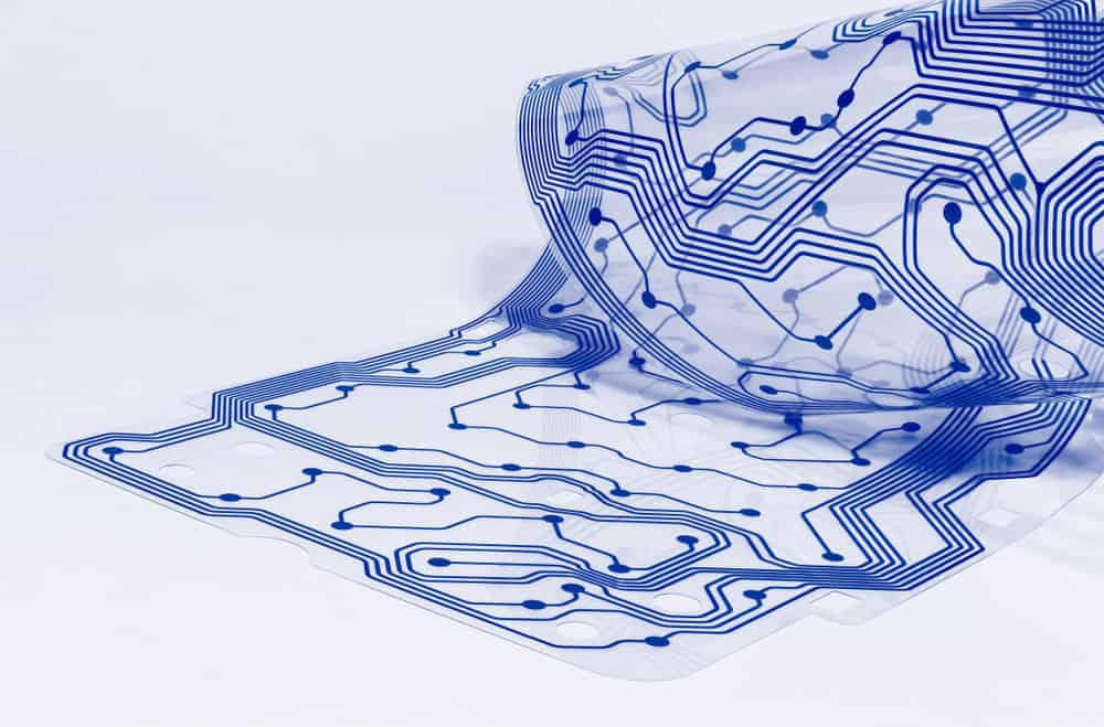
flexible PCB
What Is a Multilayer Rigid-Flex HDI PCB?
Now this is a PCB with numerous interconnections.
And its components are next to each other to provide a compact appearance regarding the circuit board.
That way, it alters the board’s general performance and helps to improve signal integrity.
Multilayer Rigid-Flex PCB Features
The multilayer flex-rigid PCB has the following features:
- First, the makeup of this circuit board comprises interconnections.
- Second, multilayer flex-rigid PCBs consist of more than three layers of conductors. Typically three to six, but it can be as many as eight.
- Also, this board’s composition combines several technologies, such as EMI shielding and surface mounting.
- To connect the rigid and flexible layer, it uses a metalized hole.
- Further, this board employs a flexible, insulating dielectric, typically polyimide. The role of the dielectric is to separate the conductors.
- Often, you’ll find that these boards use high-speed controlled impedance.
Multilayer Flex Rigid PCB Design Considerations
Buried Capacitance
This type of technology now incorporates a very slim dielectric layer capable of offering distributive decoupling capacitance.
Also, it can improve the performance of PCBs by ensuring signal integrity.
The buried aspect refers to the separation needed for capacitance to occur beneath the first layer of the board with the microprocessors.
Buried Resistance
Here, a slim film gets electrodeposited on a copper NIP metal alloy.
And it’s also referred to as the resistor conductor material.
The film gets laminated to a dielectric and then subtractively processed to provide planar resistors.
Because of its slim nature, it’s possible to bury the film inside the layers without increasing the overall thickness of the board or the occupied surface.
Thus, it’s similar to discrete resistors.
Metal Core and Metal Back
You need a board with a metal core.
Such a board is an MCPCB (Metal Core Printed Circuit Board).
The metal core dissipates heat.
Thus it has thermal conductivity.
Now the material engineers often use as the metal core is copper and aluminum alloy.
And it acts as a thermally conductive dielectric layer, allowing air to escape.
Also, this metal core eliminates the need for several heat sinks on top of the surface-mounted components.
Further, it has other prominent attributes like grounding and rigidity.
Copper and Epoxy-Filled Vias
Undoubtedly, the conductive epoxy-filled vias are ideal. After all, they can provide a more improved finished diameter, better than .008 inches and .018 inches.
Thus, regardless of whether or not it’s conductive, whatever kind of epoxy you use gets forced through the hole completely and still does not run out.
And this is precisely the relative aspect ratio that’s usually recommended in cases where the depth-to-diameter is below 10:1.
Sequential Lam and Stacked Vias
Usually, engineers use this technology in making, designing, and fabricating HDI PC-stacked vias.
Often, they use it for connecting relatively small diameter vias to route the fine-pitch components.
Multilayer Flex Rigid PCB Applications
When to Use Multilayer Flex Rigid PCBs
This circuit board is an effective solution for situations with design challenges regarding the application you intend for the PCB.
Here are some examples:
- There are unavoidable crossovers
- You must employ some special requirements to control the impedance
- There’s crosstalk you will need to eliminate
- The design calls for some additional shielding
- The design has several components and therefore entails a dense surface mount assembly
- The design’s circuitry is dense
- Ground and power plane applications
Multilayer Flexible Rigid PCB Applications
As mentioned earlier, this PCB has unique features and suitability for certain uses.
For this reason, it’s ideal for use in a wide range of applications, including:
- Communications: In general, HDI multilayer flex-rigid PCBs enable communication devices and different gadgets in the sector to function. Thus, you’ll often find these PCBs in modules, switches, routers, and semiconductors of these electronic devices.
- Medical equipment: Another place you’ll find HDI PCBs is in a wide variety of cutting-edge medical electronic devices, such as imaging monitoring and laboratory equipment.
- Aerospace and automotive industry: Often, electronic manufacturers in the aerospace and automotive industry must cram more capabilities and features into tiny spaces. To achieve this goal, they employ HDI multilayer PCBs.
- Industrial uses: Interestingly, most advanced industrial machinery today employ HDI multilayer PCB technology.
Advantages of Multilayer Flex Rigid PCBs
High Assembly Density
First, the multilayer PCB can significantly multiply its density via layering.
In that way, it can register increased functionality, capacity, and speed.
And all this is possible despite the board’s small stature.
Smaller Size
Like it is with functionality, this board uses a combination of several PCBs to create a better and more streamlined design.
Undoubtedly, combining PCBs is only possible because of the boards’ small size.
Lightweight
Another remarkable quality of this multilayer PCB is its fewer connected components.
That’s because it means the board is lightweight.
And this makes it ideal for smaller electrical devices where weight is a primary concern.
FAQs
What Is the Difference Between a Rigid and Flexible PCB?
In the case of rigid PCBs, these are circuits set or built upon a rigid surface that cannot bend.
In contrast, the flexible PCB circuit gets built upon a flexible base that can bend and fold.
How Many Layers Are in a Flexible PCB?
Now most flexible PCB stack-ups comprise four layers.
However, it’s not uncommon to see up to 12 layers of flex.
That said, always remember that in most cases, the greater the number of flexible layers, the harder it will be to bend the PCB.
What are Flex PCB Materials?
Usually, most flex PCBs comprise a polyimide film as the substrate, adhesive, coverlay (polyimide), copper, and copper foil.
Conclusion
Now you understand better the functionality, features, and applications of the multilayer flexi rigid PCB.
The design trends we’re seeing today call for an increased demand for multilayer flex-rigid circuits.
That’s because, as we’ve seen, these boards offer reduced dimensions and weight and superior performance in the most extreme of environments.