
How to solder on flexible PCB is a commonly asked question, considering how fragile these boards are and how tiny the components are.
So if you’re wondering how to get it right, this article outlines DIY steps to solder onto a flex PCB, some design and layout considerations, and tips to ensure you make no mistakes.
Table of Contents
- What Is Flex Soldering?
- DIY Steps on How to Solder onto a Flex PCB
- Design and Layout Considerations for Soldering on Flexible PCB
- Tips to Ensure Successful Soldering on Flex PCB
- FAQs
- Conclusion
What Is Flex Soldering?
Flex soldering is when you solder to join a flexible printed circuit board, also called a flexible circuit, to another surface or component.
To solder, you heat a metal alloy, typically tin and lead, until it turns molten and then use it to join two metal surfaces.
So in our case, flex soldering, you’ll affix a flexible circuit to the surface or component by first applying solder to the contact points on the flexible circuit.
In the electronics sector, engineers employ flex soldering to join FPBCs to other parts like sensors, displays, and connections.
Doing so permits a dependable and secure connection while preserving the flexibility and bendability of the flexible circuit.
DIY Steps on How to Solder onto a Flex PCB
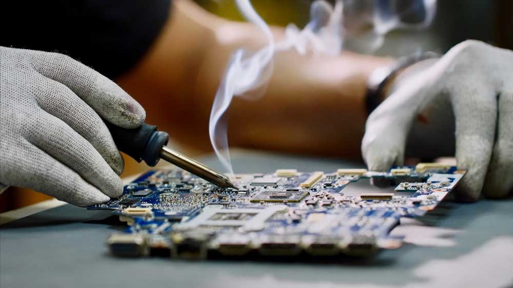
(Caption: Engineer soldering on flexible PCB)
You can succeed at soldering onto flex PCB with the right tools and technique.
First, let’s look at the primary tools you need for the job:
- Soldering iron
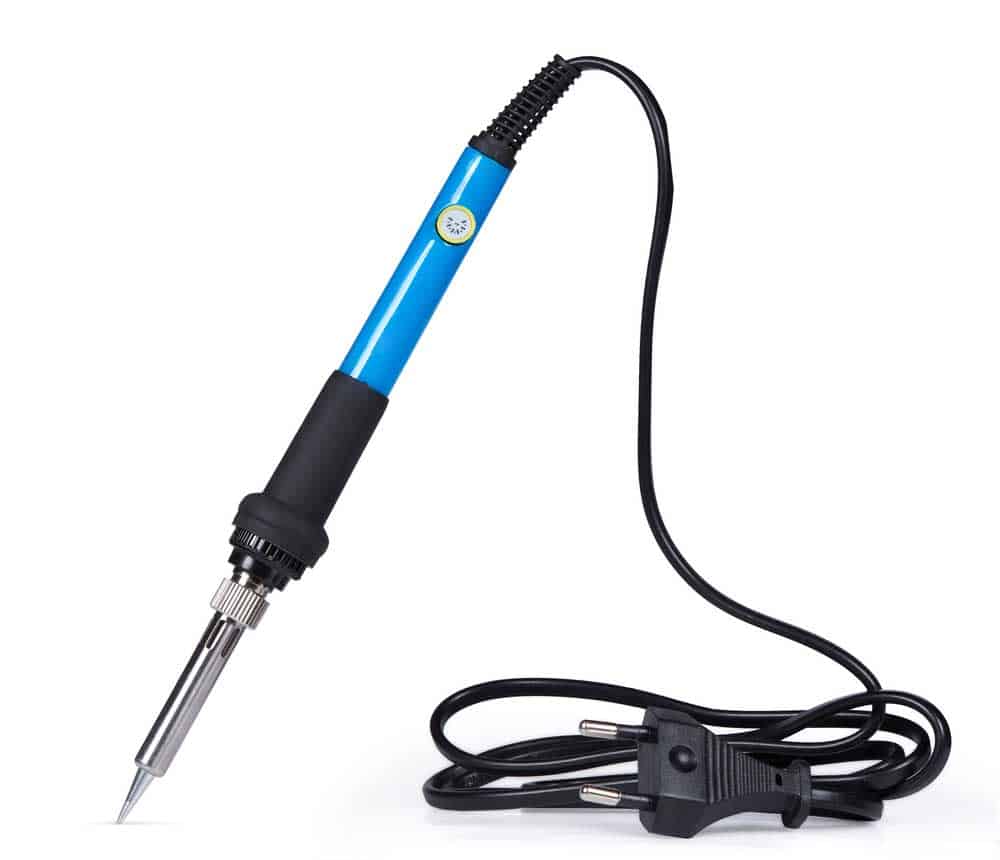
(Caption: Soldering iron)
- Solder wire
- Flux
- A set of tweezers
Now let’s move on to how to do the job:
- Set up your workspace: First, select a spotless, well-lit, and airy space, and ensure that you have at least all the must-have tools mentioned above. Then prepare the board by cleaning the area you want to solder with a soft, lint-free cloth. If you find that there’s still some flux or debris residue, then a cleaning agent will help remove the dirt.
- Get the soldering iron ready: In this step, remember that the one you need here has a fine tip and a temperature control feature. Once you have the appropriate soldering iron, set the thermostat to 250 to 350 degrees Celsius.
- Tin the soldering iron: Ensure you have cleaned the tip and tinned it lightly with the solder. To tin, apply some solder to the joint and place one end of the component on it. Now using the tweezer, clamp the component and solder that end to weld it.
Apply flux: The next step is to apply a little flux on the solder pads and the pins at both corners. As you do that, lightly touch the pad, allowing the solder to flow onto it. That way, besides letting the solder flow, you also reduce oxidation, which would result in poor soldering.
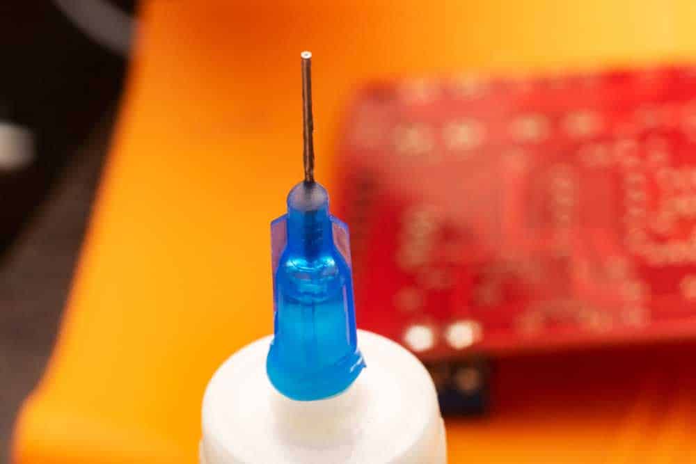
(Caption: Solder flux)
Remember, you only require enough solder to produce a glossy surface.
So avoid any bridge or extra solder on the pad. Also, remember that you need not apply any flux if it chips you’re soldering onto the board.
Position the component by soldering it:
Apply a light contact using the soldering iron tip onto the component’s pad, allowing the solder to flow and form a junction.
While you do this, ensure that you hold the soldering iron so that its tip remains parallel to the pins.
That way, you prevent solder bridges.
Check the joint:
Next, check the joint for bridges, extra solder, or other flaws.
To do this, you might need to use a magnifying glass.
Then, repeat the process until you have soldered all the components onto the board.
Clean the board:
Lastly, use a suitable cleaning agent once you have sold all the components.
That means one with no harsh chemicals to clean the flexible PCB gently.
Design and Layout Considerations for Soldering on Flexible PCB
Due to the nature of the materials the flexible circuit comprises, there are specific factors to consider when soldering onto these boards to avoid flexible PCB issues:
- First, flexible circuits consist of thin, flexible materials like polyamide. High temperatures and mechanical stress easily damage these materials.
- Second, choose a shape and size of solder pads that minimize the stress on materials during soldering as much as possible.
- Further, the adhesive system used in soldering on flexible circuits differs from that used on regular PCBs. See, because a flexible circuit must be able to bend, the adhesive used on it is “softer” and less cohesive to allow movement. But there’s a caveat to this feature. The adhesive can soften a little when exposed to high temperatures. So you want to use anchor spurs to make up for this problem.
Tips to Ensure Successful Soldering on Flex PCB
Here are some pointers to help you solder onto flex PCBs successfully:
Avoid Stacking Conductors on Multiple-Layer Boards
Often, stacking occurs on adjacent layers, and the reason engineers do it is it helps minimize electromagnetic interference (EMI).
But the problem is it increases the overall thickness of the board, creating an I-beam effect.
Therefore, if you must employ this EMI reduction technique, stagger all the line pairs.
Ensure Adequate Heat Release
An electronic device that does not release heat well is vulnerable to damage due to overheating.
Similarly, without adequate heat release, a flexible PCB would overheat, damaging the delicate circuitry of the board.
Therefore, engineers must ensure the flexible PCB dissipates heat appropriately.
And the most straightforward way to achieve this is to ensure the components used have a great surface area to volume ratio.
For example, opt for compact designs as these shorten the thermal path.
Ensure There’s No Bending on the Soldering
In particular, ensure there’s no bending on the soldering pads.
See, pressure caused by bending is much higher in flexible circuits than in standard boards, and this stress can strain the board, eventually causing the copper traces to fail. To prevent this,
- Laminate the back side of the flexible PCB using double back scotch tape or overhead transparency film.
- Use a clean, flat, smooth work surface so the soldering pads don’t bend.
- Use clamps to ensure the flexible PCB does not slide while you’re soldering.
- Use a thicker stiffener and apply it close to the accelerator solder joints.
Remove Soldering Residue
Here, you’re cleaning off flux or rosin residue. And the reason you need to be keen is that the components are tiny.
So, you’ll need a no-clean flux to remove the residue.
Also, when soldering, you want to use a low-residue solder paste to ensure as little residue as possible remains.
Also, a no-clean flux pen. Further, make sure the tip of your solder iron is clean.
Pot Solder the Joints
It would be best if you potted solder the joints to keep them from flexing and breaking.
To pot solder, apply 5-minute epoxy on the accelerometer’s edges.
But remember that a lot of mechanical stress can build up at the edge of the potting area.
This pressure can lead to failure.
Therefore, avoid concentrated T potting substances as because of the mechanical stress buildup already there, these compounds can break the solder bonds.
Use Small Amounts of Solder Paste
Usually, solder paste comes in a large jar or syringe, yet components are minute in size.
It’s no wonder there’s an automated process (pick-and-place machine) for mounting SMT components.
However, if you have to do it by hand, use a tiny applicator to guarantee you use a small amount of the paste.
You can also use a stencil as it guarantees uniform application and in the appropriate quantity.
Ensure Low Soldering Temperature
Generally, flexible PCBs tolerate much less heat than rigid PCBs.
So, as a rule, you should never use the same temperature on a flexible circuit as you would on a standard PCB.
Otherwise, you risk causing delamination and blistering.
Instead, use low-temperature solder alloys to guarantee a low soldering temperature, typically 250 to 350 degrees Celsius.
And if you’re unsure of the temperature profile, seek guidance from a reputable PCB manufacturer, although it’s just best to stick to the lowest temperature possible.
Additionally, you want to use a soldering iron with temperature control features.
FAQs
What Temperature Do You Solder Flexible PCB?
Generally, the components and type of solder you use will determine the temperature at which you should solder a flexible printed circuit.
But the recommended temperature is anywhere between 250 and 350 degrees Celsius.
Which Conductor Should I Use in Flexible PCB Soldering?
Well, the application requirements, operational circumstances, and design considerations all play a role in selecting the most suitable conductor for flexible PCB soldering.
For example, thin, flexible copper foils that flexible PCBs comprise get bonded onto a flexible substrate like polyester or polyamide film.
What Is the Easiest Way to Attach Components?
Because SMT components are so tiny, automated pick-and-place machines do the job of placing the components.
Therefore, engineers often use these.
That said, you can attach components by hand using an applicator.
Conclusion
That’s how to solder on a flexible PCB. Granted, it’s a challenging task requiring skill and meticulous attention to detail.
However, if you adhere to the instructions and tips outlined above, you can properly solder your flexible PCB.
And with practice, you can confidently take on any flexible PCB soldering project.