
After manufacturing and assembling a printed circuit board, you must ask yourself how to terminate flex PCB.
Terminating a flex PCB is easy if you know the right steps.
However, depending on the application, you can do so in multiple ways.
Moreover, as flexible PCBs increase in demand, so is their popularity in consumer electronics and industrial applications.
And all the systems need a flex PCB to terminate differently.
So, do you know the methods to terminate a flex PCB?
If not, today’s article is for you. Let’s get rolling.
Table of Contents
- What Is Flex PCB Termination
- Why Terminate A Flex PCB
- Common Flex PCB Termination Methods
- FAQs
- Conclusion
What Is Flex PCB Termination
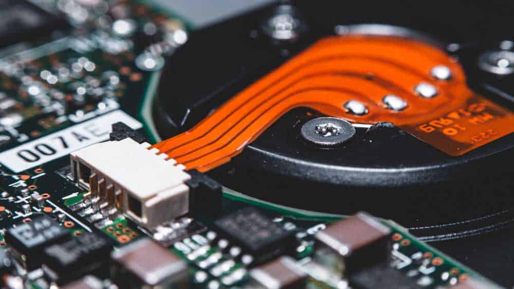
(A flex PCB terminating onto a hard drive circuit)
Generally, after design and manufacturing, the next step is assembly in the production process of a printed circuit board.
After assembly, you must ensure that your flexible PCB matches the system you will install.
Additionally, you must ensure that the impedances match so you don’t lose power.
As such, system termination ensures that the flex circuit board and the appliance match characteristics.
Additionally, it is a process of ensuring that the system functions well after a proper installation.
Why Terminate A Flex PCB
Manufacturers terminate flexible PCBs to establish an electrical connection between the circuit board and the components of the system.
For instance, they ensure that electrical signals flow properly between both systems for better functioning.
If they fail to do so, the consequences are that the system will fail to function as per the design considerations.
Additionally, you will experience issues like intermittent connections and poor signal quality, which may reduce the effectiveness of your appliance.
Moreover, extreme cases may experience complete system failure.
A proper termination ensures your PCB has proper mechanical stability.
Generally, flexible printed circuit boards can bend or flex but still need proper support from other surfaces or boards.
Consequently, proper termination provides an excellent surface for the flex PCB to terminate and flex without damage.
Common Flex PCB Termination Methods
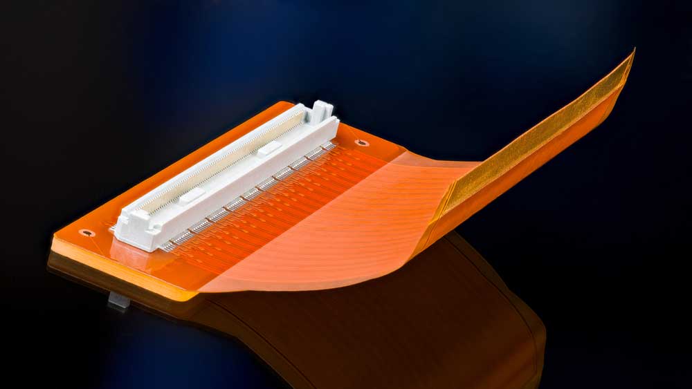
(A flex-printed circuit board with a white connector)
Several methods exist to attach a flexible PCB to its system without causing massive interruptions.
Additionally, the following methods ensure your system won’t undergo any system distortions or interruptions.
Here, let’s look at some methods that you can employ.
Series Termination Method
The series termination method whereby manufacturers place a resistor close to the driver.
Therefore, system impedances are close to that of the printed circuit board conductive traces.
An advantage of this method is that it lacks a direct current (DC) value.
In other words, it doesn’t lose power through the resistor.
However, it suffers because it cannot estimate the proper resistance resulting in the subsequent value failing to reflect the true signal integrity.
Parallel Termination Method
A parallel termination method is the most popular termination technique for flexible printed circuit boards.
Usually, it’s a technique that circuit board professionals use for high-speed signals.
It involves placing a receiver in parallel to a shunt resistor, whereby you place the receiver as close as possible to the termination resistor.
Additionally, you must ensure that the resistance and inductance values are as close as possible to the line impedance value-wise.
The termination will be ineffective, and your system or appliance is bound to fail under stress.
In this method, you should connect the resistor to the Vcc or ground for an effective termination.
Furthermore, the matching resistor absorbs most reflections at the furthermost end of the flexible circuit board connections.
However, the system experiences power losses as a small percentage of the power flows through the resistor leading to more excellent power dissipation.
ZIF Connectors Method

(Consumer electronics have different types of connectors)
Zero Insertion Force (ZIF) connectors need minimal force to insert, and we use them for applications that require frequent connection of the flex PCB.
They are easy to design and come in several configurations that lower the chances of flex PCB damage during installation.
Moreover, they have through-hole terminations, surface mount connections, and even right-angle orientations.
The advantage of using the ZIF connector method is that you don’t need a mating connector as the PCB ends mate directly to the PCB.
LIF Connectors Method
The low insertion force (LIF) connectors method needs minimal force to insert and extract from the flex PCB.
Therefore, we use them in applications whereby you don’t remove the flexible PCB frequently.
Moreover, we use them in applications with minimal space, like computer motherboards and consumer electronics.
FFC Connectors Method
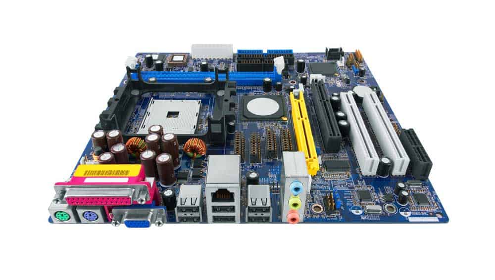
(Computer motherboard with different connector sockets)
Electronics manufacturers use flat flexible cable connectors to connect a flexible PCB to an FFC connector.
Generally, the connectors have low profiles; you will find them in most consumer electronics like camcorders and digital cameras.
Additionally, the FFC connectors have male and female contacts that fit into each other easily.
Therefore, installing and uninstalling them is easy for better reliability.
Z-Axis Connectors
Z-Axis connectors allow manufacturers to connect vertically to the PCB’s surface.
Consequently, we use them in applications found in low-space areas forcing one to make a vertical connection.
Moreover, manufacturers design it with proper tolerances and measurements to ensure that both ends align well.
FAQs
How do you attach a connector to a flex PCB?
Attaching a connector to a flexible circuit board is generally easy for most applications.
However, the challenge is that you must design the connector to be compatible with the accompanying system before connecting the two.
First, use isopropyl alcohol and a lint-free cloth to clean both surfaces.
The presence of debris interferes with the electrical integrity of both systems.
Second, align the connector’s terminals with those of the flexible PCBs before applying non-conductive adhesives.
At this step, ensure that the adhesive you use is compatible with the system so you don’t lower its mechanical and electrical stability.
Thirdly, use a jig or an adhesive to hold the connector in place while ensuring a proper connection.
Fourth, wait for the adhesive to set before soldering the connector contacts to the flexible PCB.
Fifth, test the flexible PCB to ensure it is also functioning.
What are the benefits of PCB termination?
Proper termination is important for your PCB to ensure that it works well in the system you are installing.
It also facilitates proper signal transfer to minimize losses when matching two systems.
Among the benefits of PCB termination is the ability to match a flex PCB with different devices.
Moreover, matching a signal’s impedance to a receiver reduces the chances of reflection, improving compatibility.
Second, matching both systems reduces unnecessary noise, lowering signal transfer between both systems.
Furthermore, it lowers electromagnetic interference resulting in more predictable system performance.
Is it possible to terminate a PCB without connectors?
Yes, you can terminate a flexible PCB without connectors if the system has other ways of ensuring proper signal transfer.
For instance, you may use pins that fit directly into a socket.
However, since you must consider future maintenance, using a connector is a better way to go, as you can easily disconnect.
Moreover, signal integrity is important in electronics, and we must use systems that don’t interfere with its transfer.
Therefore, if you have a project on flexible PCB, we recommend terminating it with connectors.
Conversely, a PCB that lacks connectors must have direct solders or pins for attachment.
To work efficiently, you must ensure signal integrity between the flex PCB and the installation system.
However, direct solders and pins may not work as well as connectors, lowering the flex PCB’s use.
Conclusion
Generally, most manufacturers will conduct tests to ensure that connectors terminate to the flex PCB well.
Moreover, depending on the application, they must ensure they use the right termination.
Failure to do so will lead to inconsistencies or even system failure.
If you have a flexible PCB project, ensure you know how connectors terminate to save on space and resources.
Luckily, we have gone through some major connectors you can work with.