
A flexible PCB structure is crucial for engineers and designers when developing circuit boards and electronic devices.
Unknown to many, flexible PCBs have a unique structure that differs from rigid boards.
However, like rigid boards, we can still classify them as multilayer, double-layer, and single-layer circuit boards.
And while the number of layers might differ, the core structure of flexible circuit boards remains the same.
So what does it entail? Well, Keep reading to find out everything related to flexible PCB structure.
Table of Contents
- PCB Evolution
- Flexible PCB Structure
- Flexible PCB Structural Types
- Flexible PCB Structural Materials
- Fundamental Flex PCB Structural Applications
- Flexible PCB Design Specifications
- FAQ
- Conclusion
PCB Evolution
Flexible circuit boards have not been around for long like rigid boards.
Surprisingly, PCBs came into existence in the 20th century, and even though they have been evolving with new technologies, their fundamental design has remained unchanged.
The advancement and increased adoption of PCB technologies has forced PCB manufacturers to speed up the adoption of better semiconductor packaging technology.
As a result, manufacturers can now develop compact and smaller electronic devices.
Moreover, the need for circuit boards that fit into tighter spaces and work well under harsh conditions has accelerated the development and adoption of flexible circuit boards.
For this reason, the 21st century has seen a rise in wearable products, including interactive clothing, smartwatches, and VR/AR glasses.
Also, there has been increased development of smartphones with foldable displays and wearable medical devices to monitor human health.
Flexible PCB Structure
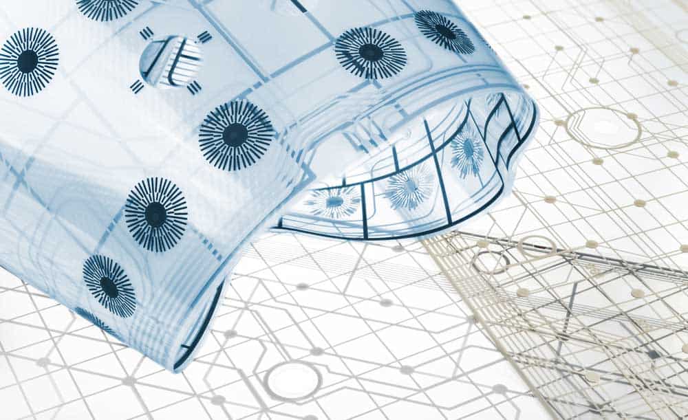
(A blue electronic flex circuit board curled)
Every flex PCB manufacturer or designer should understand its structure to develop a flawless product.
Interestingly, we also classify flexible circuit boards into single, double, and multi-layer PCBs like rigid boards.
While the number of layers might differ, the core structure of flexible PCBs remains the same.
Almost all single-layer flexible circuit boards have a dielectric film as the base material.
This material is mainly polyimide designed to be traction and temperature resistant.
Also, we have conductive copper as an important aspect of the structure.
Generally, it has circuit board traces, which help with signal transmission.
Moreover, there is a protective finish having a coat or overlay.
Completing the single-layer structure are adhesives which include polyethylene or epoxy resin.
Surprisingly, we drill the protective coating to allow solder pads and etch the copper to get traces.
However, with increased components and complexity, the need for more layers becomes a reality.
Therefore, a manufacturer is presented with the option of picking multilayer or double-layer circuit boards.
A major difference between multilayer and single-layer PCBs is that multilayer options have plated through holes.
We use these holes to connect multiple flexible PCB conductive layers.
Flexible PCB Structural Types
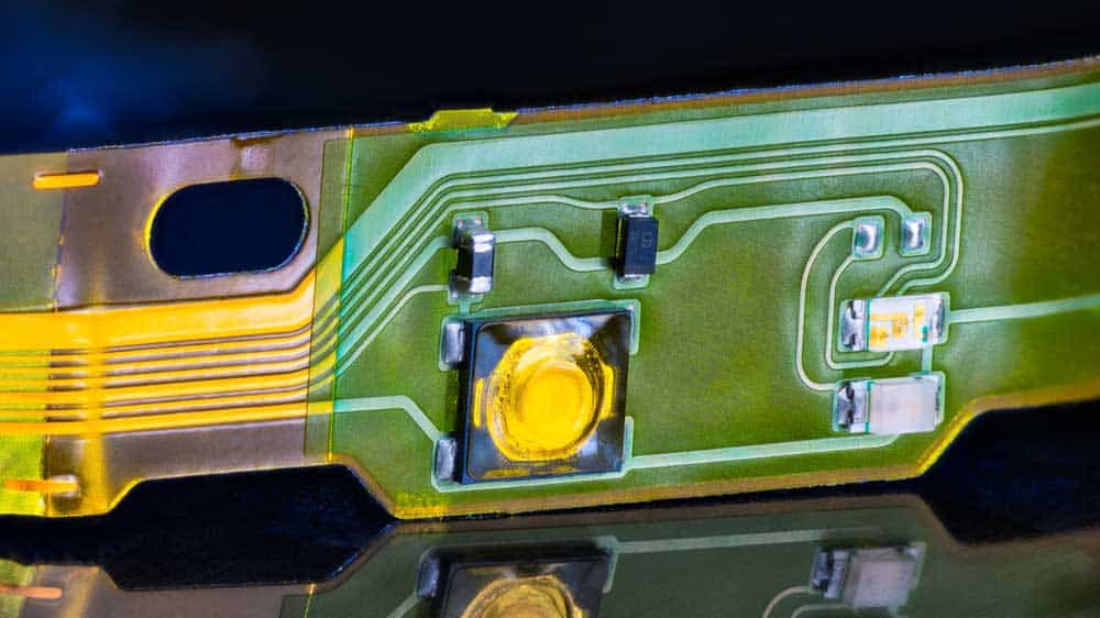
(Electronic flex printer circuit)
There are five flexible PCB types, as we’ll discuss below:
Single-Layer Flex PCBs
This flexible circuit board has one conductive copper layer on a bendable dielectric substrate.
Additionally, the conductive copper is only on one side of the substrate.
You use these boards when you’re not connecting many components in the circuit.
Double-Layer Flex PCBs
Unlike the single-layer PCB, this option has two conductive layers on either side of a bendable dielectric substrate.
Therefore, it lets you connect components on both sides of the board.
You can use these circuit boards when you need to connect many components.
Multilayer Flex PCB
This is our final option for categorization based on layer count.
The boards have at least three conductive copper layers separated by bendable dielectric materials.
HDI Flex Circuits
Besides classification based on layer count, we can also categorize flexible PCB depending on the configuration.
First on our list is the HDI flexible PCB which involves high-density connections.
Generally, these circuit boards feature better efficiency, reliability, construction, design, and layout.
Moreover, these boards have reduced flexible materials and contain high electrical performance.
Lastly, they have a reduced package size.
Rigid-Flex PCB
The rigid-flex PCB adds some rigid circuit board features to a flexible board.
For example, although the boards are flexible, they are firm enough to support component attachment.
Furthermore, they support high-density components.
Flexible PCB Structural Materials
Below are the main materials we use to create flexible circuit boards:
Substrate
Polyimide film is the most common substrate and can bend without damage.
However, you can still use other substrates like polyethylene naphthalate.
Manufacturers prefer polyimide to other substrate materials because of its high-temperature resistance.
Therefore, they won’t melt and can be elastic even after thermal polymerization.
Adhesives
We use adhesives to bond the different layers and ensure connectivity.
In the past, flexible circuit board manufacturers employed pure adhesives, reducing circuit reliability.
Therefore, they came up with adhesive-free PI.
Conductor Materials
Flexible PCB requires conductor materials to transmit current and signals.
Thanks to its high conductivity, copper is the most common material for this purpose.
Also, copper is less costly and readily available compared to other materials like silver and gold.
Moreover, copper is excellent at heat dissipation, thus emitting heat from the board faster.
How much current a copper material conducts through a circuit depends on its thickness.
Insulators
How do you protect circuit board users from dangers such as electrical shocks?
The best solution is to use an insulator cover over the conductive copper layer.
The best insulating material for circuit boards is a polyimide film.
Fundamental Flex PCB Structural Applications
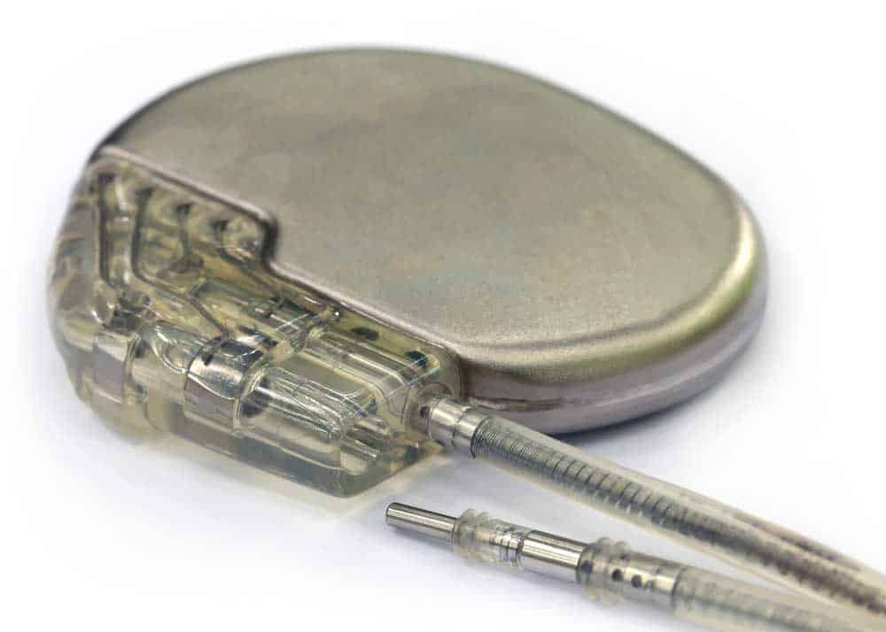
(A pacemaker that uses flexible PCBs)
Flexible circuit boards have limitless application options. Check them out below:
- Consumer electronics: This is the common application of flex PCBs and includes electronics like calculators and smartphones.
- Telecommunication devices: Flex PCB compactness facilitates use in telecommunication devices like satellites and GPS trackers.
- Medical devices: Recently, we have seen a growing trend in wearables for monitoring human health. Flexible PCBs’ small size and compactness are responsible for creating devices like pacemakers and hearing aids.
- Automobiles: Flexible PCBs are major in creating automobile parts, including antilock brakes and fuel pumps.
Flexible PCB Design Specifications
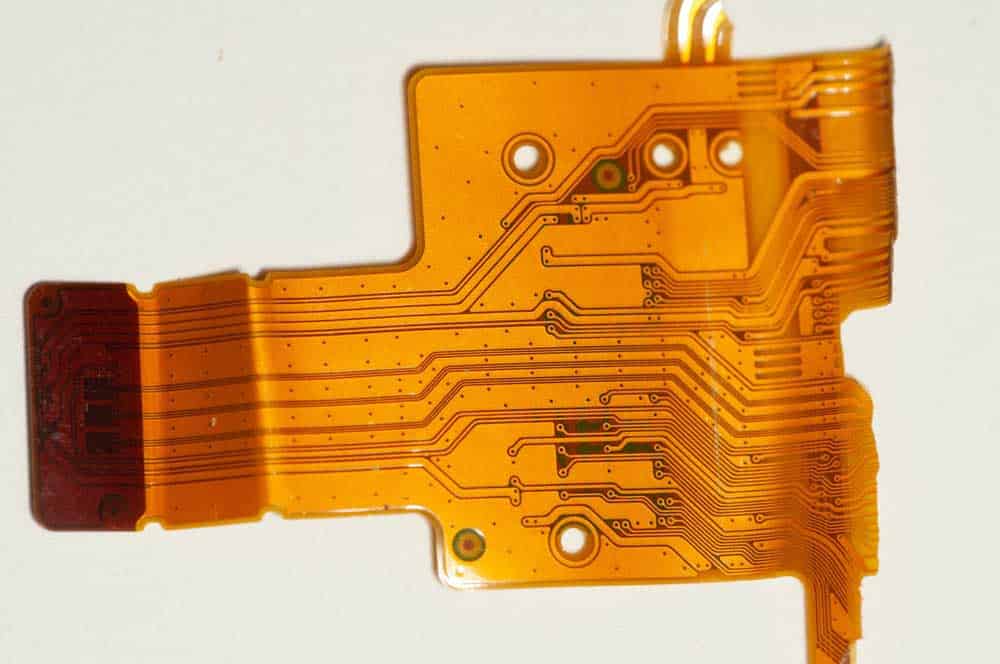
(A detailed flexed PCB)
Consider the following specifications when designing flexible circuit boards:
- Copper weight: The expected application will determine the weight of copper you use. Additionally, copper weight impact PCB flexibility. For example, a double-layer PCB uses more copper than a single-layer circuit board.
- Spacing: The spacing should be wide enough since small spacing might cause short circuits.
- Trace widths: The trace width depends on the application but should be wide enough to avoid functionality problems.
- Hole size: The hole size depends on the board’s flexibility. But generally, the holes should be tight enough to hold the components on the substrate and improve performance.
- Quality tests and compliance: Quality tests guarantee that your PCB meets quality standards. A perfect flex PCB should be lightweight, flexible, easy to install, and high-performance. However, proper quality testing should be left to competent engineers.
- Flexibility and bendability: First, we define whether the PCB is dynamic or static based on the number of times we want to flex it. A dynamic can bend thousands of times throughout its lifespan, while a static one only bends a few times. Also, it would be best to determine the bend radius earlier during the design process. Therefore, avoid a bend radius of 90 degrees.
- PCB materials: The material you use determines many things, including manufacturing cost, conductivity, flexibility, and durability. For the substrate, conductive material, and adhesives, use polyimide, copper, and epoxy.
- Flex trace routing: Consider the PCB routing since the layout determines functionality. For example, avoiding I-beaming will help avoid stress. Also, the trace must be perpendicular to the bend.
FAQ
What is a flexible PCB?
A flexible circuit board is just the opposite of a rigid board.
This board can bend without breaking or damaging the parts and components.
Therefore, most designers use these boards to develop compact and small-sized products.
Applications include wearable products, satellite devices, and medical equipment.
What are the benefits of flexible PCBs?
Generally, flexible circuit boards have the following benefits:
- They support high-density applications
- Reduced assembly cost and time
- The board presents design flexibility
- Reduced package weight and size
- Better heat dissipation
- Increased resistance to harsh operating conditions like temperature and vibrations
Do flexible PCBs have downsides?
Yes, nothing is all that perfect, and even the best products present some shortcomings.
Flexible circuits are not any different. Check out their downsides below.
- If you don’t handle them properly, they’ll damage easily
- They have a high initial design and layout cost
- It has a complex assembly process
Conclusion
Flexible circuit boards offer a great alternative to standard circuit boards.
Although the two employ almost similar materials, flexible boards can comfortably bend without damage.
Also, manufacturers prefer flex PCBs for their design flexibility, reduced package weight, and support for high-density applications.
Furthermore, flexible boards have less assembly cost and time and better heat dissipation.
However, be ready for a complex assembly process.