
One of the important features of flex PCB is the flex PCB bend radius which defines the minimum radius a board can bend without damaging the external or internal layers.
Remember, flexible circuit boards are designed to fold or bend without damage.
Generally, the PCB bend radius relies on the overall PCB design, material composition, and circuit board thickness.
Experts recommend a large bend radius to eliminate cases of breakage and delamination.
Moreover, it guarantees high durability and improved PCB performance.
However, this is just a fraction of all the flex PCB bend radius information.
Today’s article examines the circuit board bend radius with clear information on calculating it.
Let’s get rolling.
Table of Contents
- Flexible Circuit Boards
- What Is Flex PCB Bend Radius?
- Calculating Flex PCB Bend Radius
- Flexible Material Selection
- Factors Affecting The Flexibility of A Circuit Board
- FAQs
- Final Remarks
Flexible Circuit Boards
The market is full of high-quality circuit boards, with flexible boards being a reputable and effective option.
This circuit board is designed to fold and bend without damage or breakage.
Also, the board has a thin, flexible material like polyimide coated with a conductive copper layer to create effective traces.
Sometimes, we use through-hole technologies to link the layers and surface mount technology to attach components.
Generally, flexible circuit boards stand out for their lightweight design flexibility, enhanced temperature resistance, and better reliability.
Moreover, manufacturers use specialized and complex technologies like roll-to-roll processing to achieve volume production.
Funny enough, you can use flexible boards in various applications, including automotive electronics, aerospace systems, medical devices, and most consumer electronics.
What Is Flex PCB Bend Radius?

(A bend flexible PCB)
The flex circuit board bend radius is the minimum radius a flexible PCB can bend without damaging the board and its circuitry.
Generally, it depends on the circuit board material, thickness, and conductive trace size and number.
We normally express it as a ratio of the radius and circuit board thickness with a smaller ratio implying that you can bend the board to a tighter radius.
This results in a smaller form factor and higher design flexibility.
However, bending the circuit board sharply might break or crack and cause electrical failure.
And since the bend radius depends on the design requirements and application, we recommend consulting an expert engineer for the appropriate bend radius.
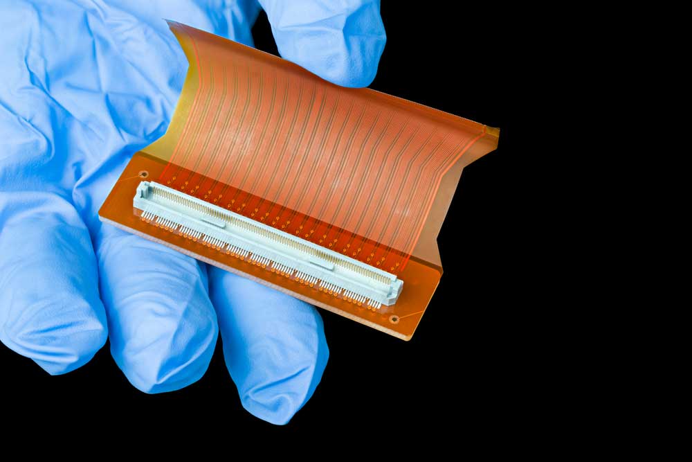
Calculating Flex PCB Bend Radius
(A bend PCB)
To calculate the circuit board bend radius, you should consider the following:
- The maximum bend angle you need for your design
- The degree of flexibility your intended application requires
- The composition and thickness of the material that makes your circuit board
- The stress level you’ll subject your flex PCB to during the application
- And finally, the conductive trace spacing and size
But generally, calculate the bend radius by multiplying the PCB thickness with the desired application height and bend radius ratio.
The minimum bend radius equation is given by:
Minimum bending radius = (r/h) x PCB thickness
Where:
R = bending radius
H = the flexible part height
The table below has the recommended bend radius of different flex PCB types based on the IPC-2223 standard.
| Dynamic | Static | |
| Multilayer | Not recommended | 20:1 |
| Double layer | 150:1 | 10:1 |
| Single layer | 100:1 | 10:1 |
Flexible Material Selection

(Bend LED flexible PCB)
If you have been in the flexible electronics industry long enough, you understand that choosing an appropriate material doesn’t happen accidentally.
Surprisingly, it’s a calculated process that guarantees product durability and reliability.
Funny enough, most manufacturers only focus on material flexibility without considering the bend radius.
This section outlines factors that should inform your material selection:
- First, your flexible material must withstand the circuit board operating temperature. This means you can use them in equipment that operates at high temperatures, like iron boxes, or at low temperatures, like refrigerators.
- Secondly, the material should be flexible enough to support the flexing and bend radius.
- Thirdly, there is a high chance your circuit board will get into contact with dangerous chemicals. Therefore, choose a flex material resistant to solvents and chemicals.
- Prolonged exposure to moisture causes corrosion, thus compromising the circuit board. Therefore, choose a circuit board that can accommodate exposure to humidity and moisture.
- The only way to get proper electrical performance is if your chosen material has appropriate properties like insulation resistance and dielectric strength.
The most important thing is working with a competent engineer or manufacturer to help you choose the right material.
All in all, the best flexible circuit board material include polyester, polyimide, and polyethylene naphthalate.
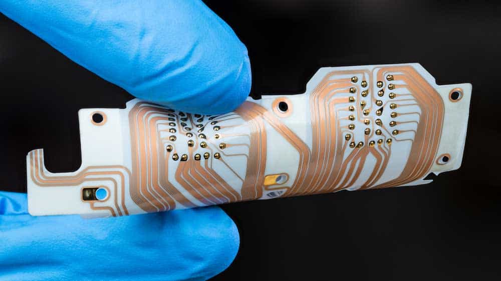
Factors Affecting The Flexibility of A Circuit Board
(A technician with gloves holding a bend PCB)
Surprisingly, the circuit board flexibility determines the manufacturing process and type of material you use.
But what factors affect the circuit board’s flexibility?
This section highlights these factors:
Material type: Isn’t it obvious by now that the type of material you use affects the flexibility of your board?
Normally, a material like polyimide will allow your circuit board to bend without damage.
Trace layout: The placement and layout of traces on the circuit board affect flexibility.
For example, placing traces in a tight configuration or closer to each other makes the board hard to bend.
Material thickness: Generally, a thinner material is more flexible than a thicker one.
However, thinner material is also more exposed to wear and damage.
Component placement: Besides trace layout, component placement affects circuit board flexibility.
The more close the components are, the less flexible the board becomes.
The manufacturing process: We have manufacturing processes like roll-to-roll processing that produce boards with high bendability and flexibility.
Flex PCB size and shape: Smaller circuit boards are more flexible thanks to the less complex angles and shapes.
Environmental conditions: If you expose your circuit board to environmental factors like temperature, humidity, and chemicals, it’ll reduce its flexibility.
FAQs
How much can a circuit board bend?
How much any circuit board can bend relies on the board thickness, the material in use, and the flexibility degree required for a particular application.
But generally, you can bend your circuit board to a radius of about 5-10 times its thickness.
However, we recommend working closely with your manufacturer or engineer for information on how much your board can bend.
What’s the minimum flexible PCB bend radius?
The minimum flexible PCB bend radius is the least allowed to bend your board without breaking it.
Generally, it is given by the following formula:
Minimum bend radius = (r/h) X PCB thickness
Final Remarks
By now, you understand there is a limit to how much you can bend your circuit board without damaging its structure.
This limit is the minimum bend radius; experts recommend ten times the circuit board thickness.
Moreover, it depends on various factors, including the flex PCB thickness and the material you have on the board.
And the larger the bend radius, the less likely your board is to damage or break.
All in all, most manufacturers produce boards with appropriate bend radii, thus limiting cases of damage or breakage.